Circuit Of Rf Transmitter And Receiver . For the receiver, the signal from the antenna is amplified in the radio frequency (rf) stage. this radio receiver consists of very few parts, an antenna, a ground, a tank circuit, a diode, a filter, and a speaker or a set of headphones. this post aims to be a complete guide for the popular rf 433mhz transmitter/receiver module. In figure 1, there are three radio stations each broadcasting at a different wavelength. the basic block diagram of an rf transmitter and receiver consists of several key components. the basic concept of operation is as follows. I’ll explain how it works, show some features and share an arduino project example with code and schematics that you can take and apply to your own projects. The essentials of these architectures are shown.
from www.youtube.com
The essentials of these architectures are shown. the basic block diagram of an rf transmitter and receiver consists of several key components. In figure 1, there are three radio stations each broadcasting at a different wavelength. this radio receiver consists of very few parts, an antenna, a ground, a tank circuit, a diode, a filter, and a speaker or a set of headphones. the basic concept of operation is as follows. For the receiver, the signal from the antenna is amplified in the radio frequency (rf) stage. I’ll explain how it works, show some features and share an arduino project example with code and schematics that you can take and apply to your own projects. this post aims to be a complete guide for the popular rf 433mhz transmitter/receiver module.
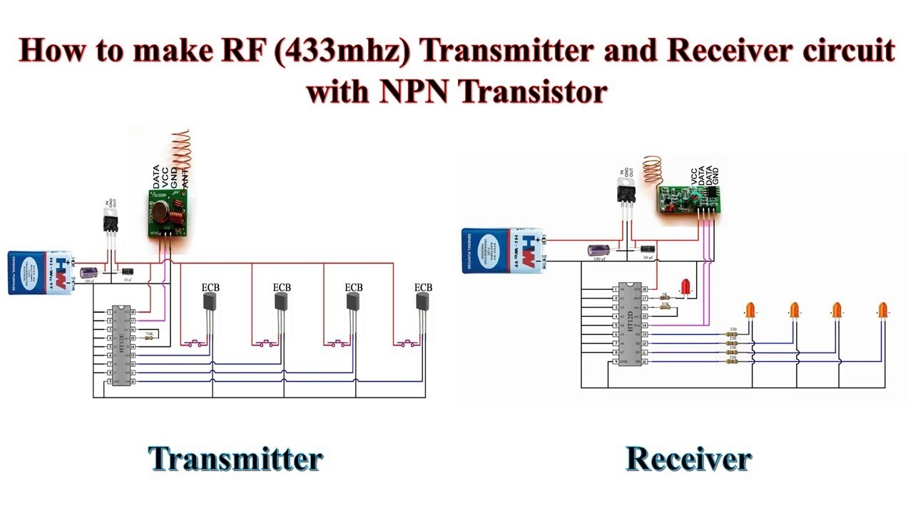
How to make RF (433mhz)Transmitter and Receiver circuit with NPN
Circuit Of Rf Transmitter And Receiver the basic block diagram of an rf transmitter and receiver consists of several key components. In figure 1, there are three radio stations each broadcasting at a different wavelength. the basic concept of operation is as follows. the basic block diagram of an rf transmitter and receiver consists of several key components. this radio receiver consists of very few parts, an antenna, a ground, a tank circuit, a diode, a filter, and a speaker or a set of headphones. I’ll explain how it works, show some features and share an arduino project example with code and schematics that you can take and apply to your own projects. For the receiver, the signal from the antenna is amplified in the radio frequency (rf) stage. this post aims to be a complete guide for the popular rf 433mhz transmitter/receiver module. The essentials of these architectures are shown.
From technicalplaces.blogspot.com
433MHZ RF Transmitter and Receiver Circuit Diagram Technical Place Circuit Of Rf Transmitter And Receiver this radio receiver consists of very few parts, an antenna, a ground, a tank circuit, a diode, a filter, and a speaker or a set of headphones. For the receiver, the signal from the antenna is amplified in the radio frequency (rf) stage. this post aims to be a complete guide for the popular rf 433mhz transmitter/receiver module.. Circuit Of Rf Transmitter And Receiver.
From exobumqvw.blob.core.windows.net
Transmitter Receiver Circuit at Levi Geis blog Circuit Of Rf Transmitter And Receiver The essentials of these architectures are shown. For the receiver, the signal from the antenna is amplified in the radio frequency (rf) stage. the basic block diagram of an rf transmitter and receiver consists of several key components. the basic concept of operation is as follows. I’ll explain how it works, show some features and share an arduino. Circuit Of Rf Transmitter And Receiver.
From experimentswitharduino.blogspot.com
Experiments with Arduino RF Receiver and Transmitter [Simple Steps] Circuit Of Rf Transmitter And Receiver the basic block diagram of an rf transmitter and receiver consists of several key components. For the receiver, the signal from the antenna is amplified in the radio frequency (rf) stage. The essentials of these architectures are shown. this radio receiver consists of very few parts, an antenna, a ground, a tank circuit, a diode, a filter, and. Circuit Of Rf Transmitter And Receiver.
From duino4projects.com
Using the 433MHz RF Transmitter and Receiver with Arduino duino Circuit Of Rf Transmitter And Receiver The essentials of these architectures are shown. the basic block diagram of an rf transmitter and receiver consists of several key components. this post aims to be a complete guide for the popular rf 433mhz transmitter/receiver module. this radio receiver consists of very few parts, an antenna, a ground, a tank circuit, a diode, a filter, and. Circuit Of Rf Transmitter And Receiver.
From dxoaomitj.blob.core.windows.net
Rf Transmitter And Receiver Arduino Projects at Johnny Epling blog Circuit Of Rf Transmitter And Receiver this post aims to be a complete guide for the popular rf 433mhz transmitter/receiver module. I’ll explain how it works, show some features and share an arduino project example with code and schematics that you can take and apply to your own projects. the basic block diagram of an rf transmitter and receiver consists of several key components.. Circuit Of Rf Transmitter And Receiver.
From kingstudio1993.blogspot.com
How to make RF (433mhz)Transmitter and Receiver circuit with NPN Transistor Circuit Of Rf Transmitter And Receiver this radio receiver consists of very few parts, an antenna, a ground, a tank circuit, a diode, a filter, and a speaker or a set of headphones. this post aims to be a complete guide for the popular rf 433mhz transmitter/receiver module. For the receiver, the signal from the antenna is amplified in the radio frequency (rf) stage.. Circuit Of Rf Transmitter And Receiver.
From circuitdigest.com
RF Transmitter and Receiver Circuit Diagram Circuit Of Rf Transmitter And Receiver the basic concept of operation is as follows. I’ll explain how it works, show some features and share an arduino project example with code and schematics that you can take and apply to your own projects. this radio receiver consists of very few parts, an antenna, a ground, a tank circuit, a diode, a filter, and a speaker. Circuit Of Rf Transmitter And Receiver.
From techatronic.com
RF transmitter and receiver with Arduino RF 433 Module Techatronic Circuit Of Rf Transmitter And Receiver For the receiver, the signal from the antenna is amplified in the radio frequency (rf) stage. this post aims to be a complete guide for the popular rf 433mhz transmitter/receiver module. this radio receiver consists of very few parts, an antenna, a ground, a tank circuit, a diode, a filter, and a speaker or a set of headphones.. Circuit Of Rf Transmitter And Receiver.
From www.circuits-diy.com
RF Based Remote Control Circuit Circuit Of Rf Transmitter And Receiver I’ll explain how it works, show some features and share an arduino project example with code and schematics that you can take and apply to your own projects. this post aims to be a complete guide for the popular rf 433mhz transmitter/receiver module. the basic block diagram of an rf transmitter and receiver consists of several key components.. Circuit Of Rf Transmitter And Receiver.
From simple-circuit.com
RF Transmitter and receiver system using PIC16F887 CCS C Circuit Of Rf Transmitter And Receiver this radio receiver consists of very few parts, an antenna, a ground, a tank circuit, a diode, a filter, and a speaker or a set of headphones. this post aims to be a complete guide for the popular rf 433mhz transmitter/receiver module. I’ll explain how it works, show some features and share an arduino project example with code. Circuit Of Rf Transmitter And Receiver.
From freakengineer.com
433MHz RF Transmitter and Receiver Circuit » Freak Engineer Circuit Of Rf Transmitter And Receiver this post aims to be a complete guide for the popular rf 433mhz transmitter/receiver module. The essentials of these architectures are shown. this radio receiver consists of very few parts, an antenna, a ground, a tank circuit, a diode, a filter, and a speaker or a set of headphones. In figure 1, there are three radio stations each. Circuit Of Rf Transmitter And Receiver.
From randomnerdtutorials.com
RF 433MHz Transmitter/Receiver Module With Arduino Random Nerd Tutorials Circuit Of Rf Transmitter And Receiver For the receiver, the signal from the antenna is amplified in the radio frequency (rf) stage. the basic block diagram of an rf transmitter and receiver consists of several key components. the basic concept of operation is as follows. this radio receiver consists of very few parts, an antenna, a ground, a tank circuit, a diode, a. Circuit Of Rf Transmitter And Receiver.
From manualdbmonika.z19.web.core.windows.net
Long Range Rf Transmitter Circuit Diagram Circuit Of Rf Transmitter And Receiver the basic concept of operation is as follows. For the receiver, the signal from the antenna is amplified in the radio frequency (rf) stage. I’ll explain how it works, show some features and share an arduino project example with code and schematics that you can take and apply to your own projects. this radio receiver consists of very. Circuit Of Rf Transmitter And Receiver.
From microcontrollerslab.com
RF Transmitter and Receiver Module Interfacing with Arduino Circuit Of Rf Transmitter And Receiver In figure 1, there are three radio stations each broadcasting at a different wavelength. this radio receiver consists of very few parts, an antenna, a ground, a tank circuit, a diode, a filter, and a speaker or a set of headphones. The essentials of these architectures are shown. this post aims to be a complete guide for the. Circuit Of Rf Transmitter And Receiver.
From www.instructables.com
RF Transmitter and Receiver 8 Steps (with Pictures) Instructables Circuit Of Rf Transmitter And Receiver this post aims to be a complete guide for the popular rf 433mhz transmitter/receiver module. this radio receiver consists of very few parts, an antenna, a ground, a tank circuit, a diode, a filter, and a speaker or a set of headphones. In figure 1, there are three radio stations each broadcasting at a different wavelength. The essentials. Circuit Of Rf Transmitter And Receiver.
From mavink.com
Rf Transmitter Schematic Circuit Of Rf Transmitter And Receiver I’ll explain how it works, show some features and share an arduino project example with code and schematics that you can take and apply to your own projects. the basic block diagram of an rf transmitter and receiver consists of several key components. this post aims to be a complete guide for the popular rf 433mhz transmitter/receiver module.. Circuit Of Rf Transmitter And Receiver.
From www.electronicsforu.com
433MHz RF Range Extender Full Electronics Project Circuit Of Rf Transmitter And Receiver this post aims to be a complete guide for the popular rf 433mhz transmitter/receiver module. In figure 1, there are three radio stations each broadcasting at a different wavelength. For the receiver, the signal from the antenna is amplified in the radio frequency (rf) stage. this radio receiver consists of very few parts, an antenna, a ground, a. Circuit Of Rf Transmitter And Receiver.
From www.circuitdiagram.co
Rf Transmitter And Receiver Schematic Circuit Diagram Circuit Of Rf Transmitter And Receiver For the receiver, the signal from the antenna is amplified in the radio frequency (rf) stage. In figure 1, there are three radio stations each broadcasting at a different wavelength. the basic concept of operation is as follows. The essentials of these architectures are shown. I’ll explain how it works, show some features and share an arduino project example. Circuit Of Rf Transmitter And Receiver.